

Roof flashing, its function and why it is important
Rain and water is one of the major weather factors that continually threaten down your roof and invade your house in the form of a roof leak. Roof flashing is as important in preventing roof leaks as are the shingles themselves. The roof flashing is a thin metal, usually painted, galvanized or can be made from copper, aluminum etc. But not all flashing is the same. There are several different types of flashing which can be used close to many details on the roof.

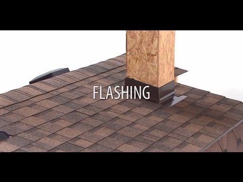
Flashings: eaves, rakes, walls, chimneys, etc.
All areas on the roof surface where roof planes intersect or protrude through the roof surface (chimneys, vent stacks, dormers, walls, etc.) require flashings. Flashing is the construction procedure which is necessary to make these areas waterproof. Metal flashings are effective, because when properly installed, they can help accommodate roof, chimney, wall, or structural movements due to settlement, expansion, and contraction. Roof flashing drains water and is constructed in a system to work with the effect of gravity. When designed and installed correctly, flashings can only be defeated by water running upward. This can happen in the presence of snow, ice or wind-driven rain.

Flashings installation
Drip edge flashing on eaves and rakes
Drip edge is the simplest flashing. It is used at the rakes and eaves. It provides efficient water shedding and protects the underlying wood from rotting. The drip edge should be made of a corrosion-resistant material that extends back at least 8 cm from the roof edge and bends downward over the fascia/roof boarding. Apply the drip edge underneath the underlayment along the eaves to allow water to shed smoothly off the roof if it gets under the shingles.
The rake flashing is installed on top of the underlayment to prevent wind-driven rain from getting beneath it.

Drip edge flashing, used on rakes and eaves

Rake flashing, installed on top of the underlayment to prevent wind-driven rain from getting beneath it.

Flashing against a vertical sidewall
Roof planes which are finished against a vertical wall at the end of shingle courses are best protected by metal flashings placed over the end of each course. This method is called “step flashing”.
These requirements for applying step flashing shingles against vertical sidewalls must be followed:
- The width of the step flashing on the deck must be at least 10 cm wide.
- The height of the step flashing installed against the vertical surface must be at least 10 cm high.
- For step flashing application, the pieces of flashing must overlap each other by at least 5 cm.
- The length of the step flashing pieces is approximately 25 cm and depends on the type of shingles being applied.
- The material used for step flashing must be corrosion resistant.

Extend the underlayment approximately 10-12 cm up against the vertical wall. Place the first flashing piece over the end of the starter strip, and finally position it so that the end shingle in the first course covers it completely. Secure the horizontal flange to the roof with two nails. Roofing nails should be placed in the uppermost 5 cm area of the step flashing piece, to avoid leakage. Next, apply the first course of shingles up to the wall. Position the second step flashing piece over the end shingle in the first row cover head-lap of the shingle. This will permit the shingle in the second course to cover it completely. Always use some bituminous mastic to bond down the shingles and step flashing. The second course of shingles follows and the end is flashed as in previous courses. Continue up the roof or sidewall area in a similar manner.
Side wall flashing can also be installed as a single continuous piece. This is common against stucco walls and with tile roofing. Be sure to turn up a hem (water stopper) on the horizontal roof side of the flashing. Metal flashings are fixed with the small clips to the roof. When you apply the shingles, do not nail the shingles through this metal profile but glue the end of every shingle on the profile edge.

Counter flashing
Counter flashing or cap flashing must be installed, lapping the step flashing or continuous metal flashing, so that water cannot run into the joint. This is done by raking out the mortar joint to a depth of 2-4 cm, inserting the bent edge of the flashing and refilling with mastic. The length of the counter flashing depends on the roof pitch and the brick size. Always start at the lowest point, overlapping each by at least 7 cm. Cap flashings can also be made as a one continuous piece.

Flashing against vertical front wall
Apply shingles up the roof until a course must be trimmed to fit the base of the vertical wall. By planning you can slightly adjust the expansion in the previous courses, so that the last row is about 15-20 cm wide. Apply a continuous piece of metal flashing over the last course of shingles by embedding it with bituminous mastic and nailing it to the roof. Do not nail the strip to the wall. The metal flashing strip should be bended to extend about 10 cm up the vertical wall and 10 cm onto the last shingle course. Applying an additional row of shingles over the wall flashing strip on the shingle surface is optional. The last pieces of shingles must be fastened with face nails sealed over with a small dab of roofing cement. The top part of wall flashing can be placed under the siding or covered by a counter flashing (stucco wall).


Soil stacks and vent pipes
Normally homes have circular vent pipes or ventilators projecting through the roof. Before installing the flashing or roofing accessory, bring the shingles up to the vent pipe. Then cut a hole in the shingle that will go over the vent pipe and set it in bituminous mastic. Be sure the flange or vent is positioned squarely on the roof. Avoid excessive use of mastic because it may cause blistering.
After the flashing is in place, continue applying the shingles. Cut the shingles in their successive courses to fit around the pipe and seal them with bituminous mastic where they overlap the flashing flange. The lower part of flashing is overlapping the lower shingles, and the sides and upper shingles are overlapping the flange. Remember, do not nail close to the pipe. Follow the same procedure where a ventilator or exhaust stack is located.

Flashings around chimneys
Because chimneys are usually built on an independent foundation that is separated from the main house foundation, the chimney can move independently of the rest of the house. To allow for chimneys and deck movement, the base flashing is secured to the roof deck and counter or cap flashing is secured to the chimney. When movement occurs, the base flashing and counter flashing will act as a movable joint. For chimneys projecting through the roof surface which are greater than 76 cm, we recommend placing a cricket behind the chimney. The cricket, sometimes called a wooden saddle, consists of two triangular sections of decking material (plywood, OSB, wooden boards) joined to form a level ridge that extend from the centerline of the chimney back to the roof deck. A cricket prevents the build-up of ice and snow at the rear of the chimney and diverts water runoff around the chimney. It also prevents water from ponding and backing up under the shingles during winter freeze or thaw periods. All roofing materials from the underlayment to the roofing shingles are applied over it.

Apply shingles up to the front edge of the chimney section. Then apply the front flashing against the front wall of the chimney. Bend the front flashing so that the lower section extends about 10 cm over the shingles and the upper section extends at least 10 cm up to the front wall of the chimney. Secure the overlaps with plastic roof cement. Use metal step flashings for the sides of the chimney, positioning the pieces in the same manner for a vertical sidewall. Secure each step flashing with bituminous mastic and nails to the wooden deck. Layer the end shingles in each course that overlaps the flashing in asphalt roof cement.
Instead of step flashing you can also install a single continuous metal flashing, which is folded together with the front and back part of the metal flashing. Be sure to turn up a hem on the horizontal roof side and secure the flashing with metal cleats. Do not nail the end shingles in each course through the metal flashing. Secure every ending shingle with bituminous mastic to the hemmed edge of flashing.
Counter and cap flashings
Counter flashing or cap flashing techniques will vary with the type of chimney finish, such as stucco, brick or stone. To keep water out of the chimney joint, begin by setting the counter metal flashing, typically copper, aluminum, or galvanized, into the brickwork or stucco. This is done by cutting out of a mortar joint to a depth of 2-4 cm and inserting the bent edge of the flashing into the cleared joint. Use one continuous piece of cap flashing for the front and one for the back part of the chimney. On the sides of the chimney, use several pieces of similar-sized flashing, trimming each piece to fit the particular location of brick joint and roof pitch. Start the side units at the lowest point and overlap each at least 7 cm side-to-side. This is a typical staggered (stepped) counter flashing for chimney or wall with mortar joints. Refill the joint when the cap flashing is installed with cement mortar, silicone caulk, or use a metal wedge and polyurethane sealant.
The continuous counter flashing technique uses a continuous metal piece instead of stepped counter flashing along the side of a chimney. It is an alternative to stepped counter flashings, which can lead to water leaks along the vertical joints in high wind or fine-grained snow.


Skylights and roof windows
Any glass structure that admits natural light through a roof can be called a skylight. Some manufacturers use the term roof window to describe a relatively large skylight placed low enough to see into the landscape. Roof windows are generally big enough to be considered an escape route in case of a fire.
Many skylight and roof window designs are being sold. Most provide their own instructions for flashing of the curb on which the skylight is mounted. The skylight curb is flashed much like a chimney. Installing self-adhesive underlayment up onto the curb is recommended. An apron flashing with a hemmed lower edge is installed on the base. A step flashing is installed on the sides; base flashing is installed upslope, holding one course of shingles away from the curb to encourage rain to wash away dirt and debris. The skylight itself provides the counter flashing or cap.

Single pitch ridge – shed roof
Occasionally, shingles are installed on a single pitch ridge (shed roof). The off flashing on a single pitch ridge turns down and just covers the top edge of the fascia board. It goes over the top and sits on top of the top course of shingles; it appears to have a layer of roofing cement under it.

Roof pitch transitions
The flashing used for pitch transitions is essentially the same whether the step pitch is on the high side, as in a porch transition, or on the low side, as on a mansard roof. The problem area is the termination of the lower course of shingles, where all the nails must be covered with transition metal strip. Therefore, the flashing must be placed under the shingles of the high slope, and overlap the fasteners on the face of the terminated shingle in the course below the transition.


Metal valley option
Roof valleys are where two sides of the roof meet, which will be the case in any gable or hip roof that has multiple roof sections. One of the installation options for open valleys is the method with the metal flashing instead of a mineral-surfaced roll. The metal flashing for roof valleys should be minimum 26-gauge (0,45 mm) galvanized steel or equivalent non-corrosive, non-staining metal with a minimum width of 60 cm. If you apply the metal valley flashing with a splash diverter and water guards on the sides which are fixed with the metal cleats, 50 cm width is permitted. Performed “W” style valleys are preferred because the center crimp helps relieve stresses on the metal without forcing the metal to buckle. The “W” shape valleys help to brake and divert water on the sides.


Special hemmed edges
Hemmed edges are used on most metal flashing systems. The hem or fold makes the flashing strong at the hem and helps control water flow. The hem can be turned up or down. Hems turned up are used at the high edge of flashings around roof penetrations, such as skylights, soil pipes and chimneys. Upturned hems are also used on the roof side of continuous sidewall flashings and on the vertical edge of open metal valleys. An upturned hem creates an air gap that resists the capillary migration of moisture from the metal to the roofing. They should never be hammered flat. Upturned hems also serve as hooks for attaching cleats. Downturned hems are used when flashings are lapped over the top of roofing or other materials, such as skylight glass.


Our roof calculator not only shows how many IKO shingles and accessories you need, also the quantity of flashing is included. Calculate now which roof components you need to complete your IKO roof!


